
INDUSTRIAL MAGNETS · ENGINEERING INSIGHTS
Preventing Magnet Cracking: Precision Countersinks for Better NdFeB Assembly
How hole geometry, screw compatibility and controlled fastening can help reduce chipping and cracking during bulk assembly.
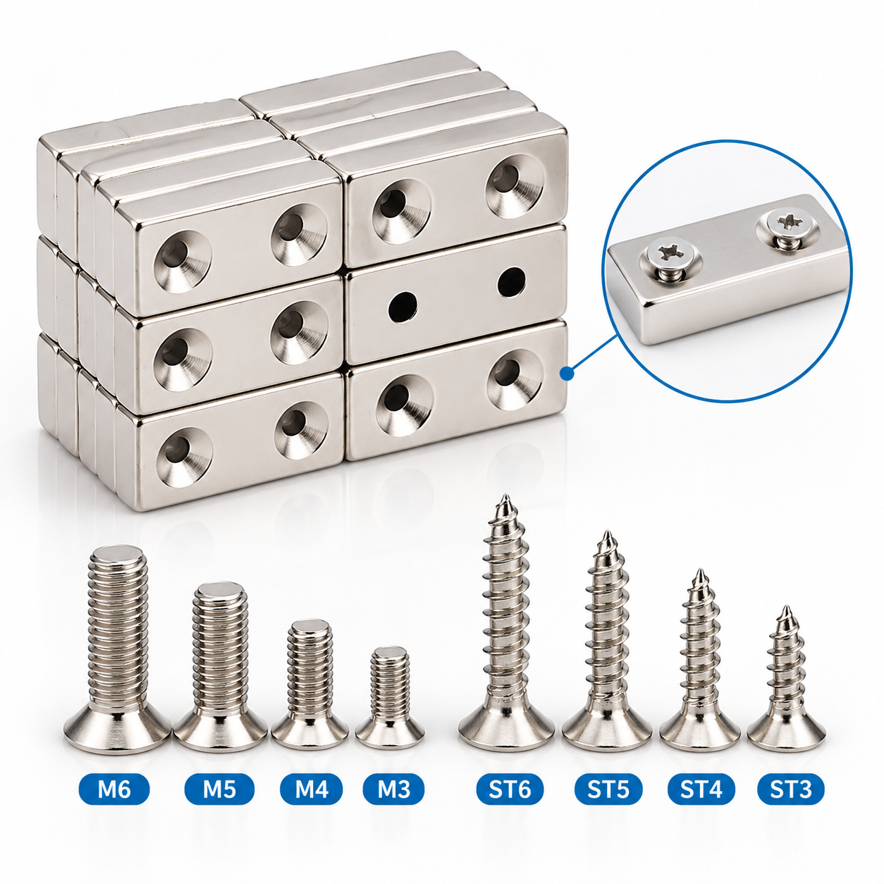
In industrial automation, precision fixtures and hardware assemblies, countersunk neodymium magnets combine screw mounting with magnetic holding. The screw secures the magnet to its base, while the magnetic surface holds a mating component.
During bulk assembly, however, manufacturers may encounter chipped hole edges or magnets that crack as screws are tightened. These failures create scrap, interrupt production and increase the need for inspection and rework.
Sintered neodymium iron boron (NdFeB) is a brittle material. Reliable installation therefore depends on more than magnetic grade or overall dimensions. Countersink geometry, machining quality, screw fit and mounting support need to be evaluated together.
The Key Assembly Question
Does the complete magnet, screw and mounting-base combination provide stable contact under the approved tightening conditions?
1. Why Do Countersunk Neodymium Magnets Crack?
Cracking during screw tightening can result from several interacting factors. Identifying the failure mechanism is more useful than simply increasing dimensional precision.
Localized Stress Around the Hole
Contact between a countersunk screw head and its angled seat produces both axial and radial load components. Uneven contact can concentrate these loads in a small area. Limited material around the hole or inadequate support beneath the magnet can further increase the risk of damage.
Machining Damage
Poorly controlled machining can leave edge chips or surface damage that may act as crack initiation sites. A smooth-looking hole does not, by itself, demonstrate the absence of microcracks. Inspection and trial assembly should reflect the application’s requirements.
Screw and Countersink Mismatch
Differences between the screw-head profile and countersink geometry can create localized contact rather than the intended bearing area. Thread size alone does not define screw-head angle, diameter or height. The complete screw specification should be checked before approving the magnet drawing.
2. What Precision Countersink Machining Should Control
The purpose of precision machining is to produce the geometry needed for the approved assembly. Tighter tolerances should be applied where they affect fit or function, rather than specified uniformly across every feature.
Hole Geometry and Remaining Material
Critical features may include through-hole diameter, countersink diameter, included angle, depth and position. The remaining material around and beneath the countersink also needs to be considered.
A shallow countersink may leave the screw head protruding. An excessively deep countersink can reduce the local section thickness. Any transition radius or secondary chamfer should be reviewed against the screw profile to avoid interfering with correct seating.
Compatibility with the Actual Screw
Provide the screw standard, drawing or physical sample during development. Confirm the head profile and required installed position using the actual mounting arrangement.
Whether the screw head should sit flush or below the magnet surface is a design requirement. The permitted position should be defined on the drawing and verified during assembly. Recess depth alone does not prevent excessive tightening.
Finished Hole and Edge Condition
Inspect the finished parts for unacceptable edge chips, visible machining damage and coating defects. Where necessary, use magnified inspection and agreed defect samples to establish a consistent acceptance standard.
Nickel–copper–nickel plating primarily provides surface protection. Coating thickness and coverage can affect final fit, so critical dimensions should be assessed in the finished condition. Plating should not be treated as a repair for cracks in the underlying magnet.
3. Inspection Priorities for Bulk Orders
Use the following checks to connect the purchasing specification with actual assembly conditions.
| Inspection Item | What to Confirm | Assembly Relevance |
|---|---|---|
| Countersink Geometry | Angle, diameter, depth and hole position | Screw seating and available section thickness |
| Hole and Edge Condition | Chips, visible damage and coating integrity | Identification of defects that may affect use |
| Screw Fit | Head profile, seating and installed height | Compatibility with the intended fastener |
| Mounting Support | Flatness, burrs, support area and hole alignment | Reduction of uneven loading during tightening |
| Pilot Assembly | Tightening conditions, damage rate and retention | Validation of the complete assembly process |
Specific tolerances, tightening limits and acceptance criteria should be agreed for the individual design and supported by appropriate validation.
4. Practical Guidelines for Assembly Engineers
Establish tightening conditions through testing.
Use the actual magnet, screw, mounting base and assembly tool. Determine a tightening process that meets the retention requirement without damaging the magnet. Do not substitute a fixed percentage of standard metal-joint torque for application testing.
Review mounting support before changing the magnet.
Check for burrs, uneven surfaces, unsupported regions and misaligned holes. Correcting these conditions may be necessary even when the magnet complies with its drawing.
Validate additional cushioning or load-limiting features.
Washers, sleeves or compliant elements can change the load path and screw seating. Assess their fit, stability and effect on the assembly before adoption rather than treating them as universal solutions.
Keep approved components and process settings under control.
Retain the approved drawing revision, reference samples, screw specification and tool settings. Review changes to the screw, coating, hole geometry or mounting base before continuing production.
Record where damage occurs.
Separate incoming damage, handling chips and tightening-related fractures in production records. Link findings to the batch, workstation and assembly conditions so corrective actions target the actual source.
Better Assembly Starts with a Matched System
Precision countersink machining provides a foundation for reliable installation. Its value depends on how well the finished magnet matches the screw, mounting base and tightening process.
For bulk orders, agree on the critical geometry and validate the actual assembly before production release. Any claimed improvement in yield should be supported by comparable batch data.